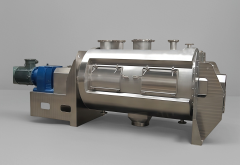
Plough Shear Mixer for Fiber-Reinforced Compounds
What Is the Plough Shear Mixer for Fiber-Reinforced Compounds?
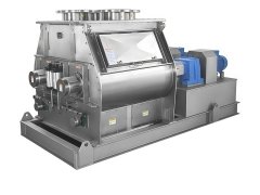
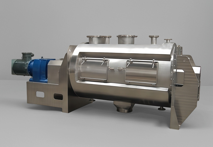
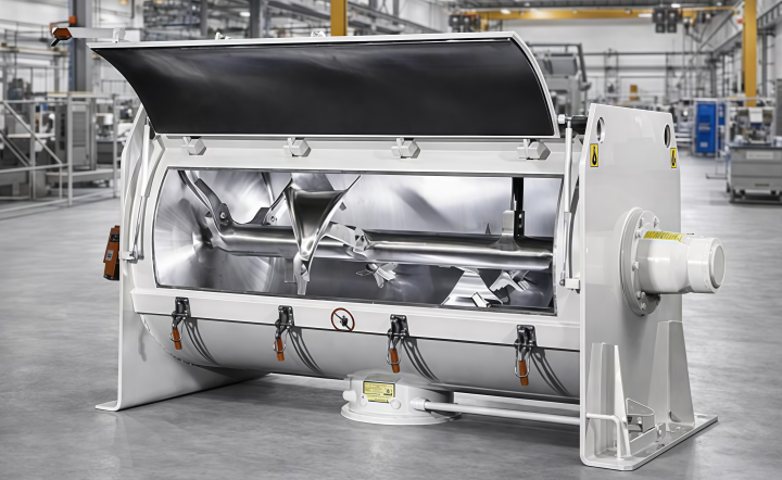
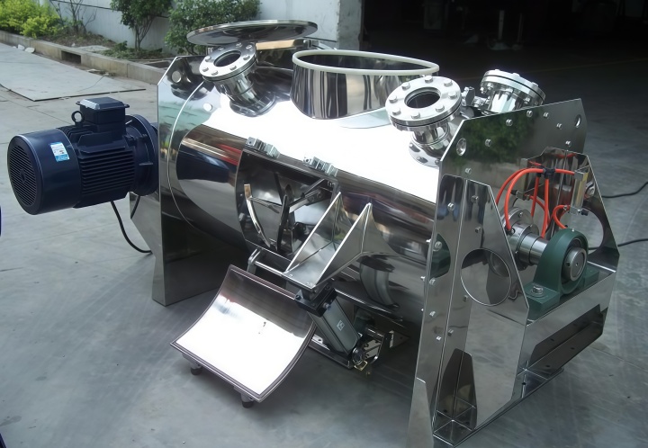
The Plough Shear Mixer for Fiber-Reinforced Compounds is a horizontal single‑shaft forced mixing unit. It is equipped with multiple plough‑shaped mixing elements mounted on the shaft, staggered along the axial direction, and works together with high‑speed chopper assemblies.
This equipment solves the primary challenges in fiber‑reinforced composite production, such as uneven fiber dispersion and fiber agglomeration. The unit can complete uniform mixing of fibers and matrix materials within three to five minutes, with a coefficient of variation of mixing uniformity controlled below five percent.
The global plough shear mixer market was valued at approximately USD 1.04 billion in 2025 and is projected to reach USD 1.73 billion by 2034.
How Does the Plough Shear Mixer for Fiber-Reinforced Compounds Work?
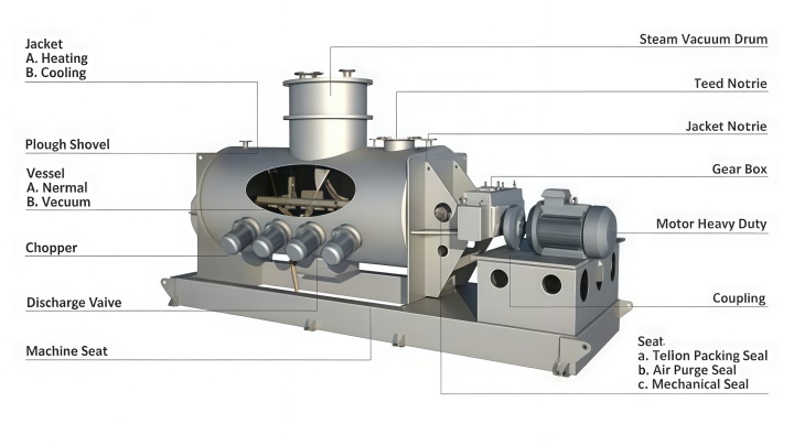
The Plough Shear Mixer for Fiber-Reinforced Compounds accomplishes fiber dispersion through two steps: macro‑convection by the ploughs and micro‑shearing by the choppers.
Macro‑mixing is performed by the ploughs on the main shaft. As the shaft rotates, the ploughs turn the material along the cylinder wall and throw it to both sides, creating a bi‑directional convective circulation and a mechanical fluidized bed effect at the plough tips. Micro‑dispersion is handled by the chopper assemblies, which rotate at a fixed speed of 1440 rpm to rapidly break up entangled fiber bundles passing through their zone.
The ploughs handle conveying and throwing, while the choppers handle cutting and dispersing. The two work together to complete the entire mixing process.
Technical Parameters of the Plough Shear Mixer for Fiber-Reinforced Compounds
The Plough Shear Mixer for Fiber-Reinforced Compounds is available in a full range of models from laboratory scale to industrial production. The total volume ranges from 0.3 to 30 cubic metres, batch capacity from 0.1 to 20 cubic metres, and filling coefficient from 0.4 to 0.6.
| Model | Effective Volume (m³) | Batch Output (kg) | Main Shaft Speed (r/min) | Drive Power (kW) |
| LDH-0.3 | 0.18 | 200 | 130 | 5.5 |
| LDH-0.5 | 0.3 | 300 | 130 | 7.5 |
| LDH-1 | 0.6 | 600 | 85 | 11 |
| LDH-2 | 1.2 | 1200 | 63 | 15 |
| LDH-3 | 1.8 | 1800 | 63 | 22 |
| LDH-4 | 2.4 | 2500 | 42 | 30 |
| LDH-6 | 3.6 | 3600 | 42 | 45 |
| LDH-8 | 4.8 | 5000 | 33 | 55 |
| LDH-10 | 6.0 | 6000 | 33 | 75 |
| LDH-15 | 9.0 | 9000 | 28 | 90 |
Chopper speed is fixed at 1440 rpm. The material of construction can be selected from 304 stainless steel, 316L stainless steel, 321 stainless steel, or carbon steel, depending on the material properties. The cylinder can be fitted with a jacket for heating or cooling, with a maximum temperature resistance of 250°C. Discharge is via a pneumatic large‑door structure.
Measured Performance Data of the Plough Shear Mixer for Fiber-Reinforced Compounds
The Plough Shear Mixer for Fiber-Reinforced Compounds delivers distinct performance when processing four common fiber types: glass fibre, carbon fibre, natural bast fibre, and lignocellulosic fibre. Each requires different chopper counts, mixing times, and temperature controls, yet all achieve low coefficients of variation.
Glass fibre chopped strands: length 3–6 mm, content 10%–30%, recommended 2–3 chopper groups, mixing time 3–4 minutes, coefficient of variation below 3%.
Carbon fibre: length 6–12 mm, content 5%–20%, recommended 3–4 chopper groups, mixing time 4–5 minutes, start at low speed to prevent fibre breakage.
Bast plant fibre (hemp, etc.): length 10–30 mm, content 10%–40%, recommended 2 chopper groups, mixing time 4–6 minutes, temperature must not exceed 80°C.
Lignocellulosic fibre: length 1–5 mm, content 5%–50%, recommended 1–2 chopper groups, mixing time 2–3 minutes, dust extraction port required.
These data are based on standard test conditions. It is recommended that users provide material samples for actual trials with the unit before finalising the model.
Key Advantages of the Plough Shear Mixer for Fiber-Reinforced Compounds
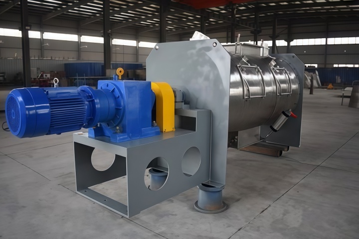
The Plough Shear Mixer for Fiber-Reinforced Compounds offers clear benefits in dead‑zone reduction, efficiency improvement, sealing and temperature control, and maintenance convenience.
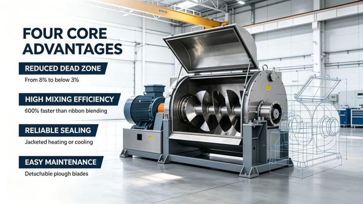
Dead‑zone reduction: With the ploughs staggered axially, the phase difference between adjacent ploughs is 180°. Measured data show that the material completes 2.3 full convective cycles per second along the cylinder axis, reducing the dead‑zone area from 8% in conventional designs to below 3%.
Efficiency improvement: Compared with ribbon blending technology, the unit delivers an efficiency increase of approximately 600%.
Sealing and temperature control: The equipment has good sealing properties and can be equipped with explosion‑proof motors. The jacketed temperature control system helps prevent heat‑sensitive fibres from degrading due to frictional heat.
Easy maintenance: The plough blades are detachable and can be replaced individually when worn.
Application Scenarios for the Plough Shear Mixer for Fiber-Reinforced Compounds
The Plough Shear Mixer for Fiber-Reinforced Compounds is used across multiple industries worldwide, including automotive, aerospace, construction, and electronics, as well as for various other materials.
Automotive industry: premixing of brake linings, friction materials, and carbon‑fibre components.
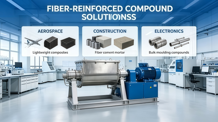
Aerospace: carbon‑fibre‑reinforced polymers and lightweight composites.
Construction: fibre‑reinforced cementitious materials and external thermal insulation mortars.
Electronics: production of bulk moulding compound parts for enclosures and computer components.
The equipment can also process glass‑fibre resin putties, ceramic clays, and refractory materials. The unit covers major markets in North America, Europe, and Asia‑Pacific, with the Asia‑Pacific region accounting for 38.5% of the global share.
Global Application Cases of the Plough Shear Mixer for Fiber-Reinforced Compounds
The Plough Shear Mixer for Fiber-Reinforced Compounds has mature applications in three major regional markets: North America, Europe, and Asia‑Pacific.
North America: Processall’s test centre in Cincinnati, Ohio, provides ongoing material testing services for global customers. Clients send 5–10 kg samples to the centre, and the test team completes mixing parameter optimisation and issues a report within three days. Over 200 customers have been served.
Europe: The mechanical fluidised‑bed process developed by Lödige of Germany has become a common technical approach for the product. Several European automotive parts suppliers use the equipment to produce carbon‑fibre‑reinforced polymer components for high‑end structural applications.
Asia‑Pacific: This region is the fastest‑growing market for fibre‑reinforced composites. Manufacturers of automotive interiors, building insulation, and electronic products widely adopt the product for large‑scale production. The global fibre‑reinforced composite market was valued at approximately USD 227.65 billion in 2025 and is projected to reach USD 459.25 billion by 2033.
Selection and Maintenance of the Plough Shear Mixer for Fiber-Reinforced Compounds
Selection Guide
Selecting the right model of the Plough Shear Mixer for Fiber-Reinforced Compounds requires consideration of four factors: batch size, fibre type and content, process temperature requirements, and material of construction.
Batch size: laboratory use – LDH‑0.3 or LDH‑0.5; pilot scale – LDH‑1 or LDH‑2; production scale – LDH‑3 and above.
Fibre type and content: high‑density fibres such as glass and carbon require higher drive power.
Temperature control: processes requiring heating or cooling should choose a jacketed configuration.
Material of construction: 304 SS, 316L SS, 321 SS, or carbon steel can be selected.
It is advisable to conduct trials with actual material samples before finalising the model.
Unsuitable Materials
Although the product works well for most fibrous materials, caution is needed in two situations.
When fibre content exceeds 60% and the matrix is a high‑viscosity resin, the chopper shearing force may be insufficient.
Continuous long fibres longer than 50 mm without pre‑cutting may wrap around the main shaft.
Routine Maintenance
Daily maintenance focuses on three aspects: sealing, bearing lubrication, and cylinder cleaning.
Main shaft seals: use combined pneumatic seals to block fibre powder from entering the bearings.
Chopper bearings: regularly check lubrication status.
After each mix, clean residual material from the inner wall and ploughs.
If mixing uniformity decreases, inspect the chopper blades for wear; they can be replaced individually.
Frequently Asked Questions about the Plough Shear Mixer for Fiber-Reinforced Compounds
What fibre lengths can the Plough Shear Mixer for Fiber-Reinforced Compounds handle?
The product can handle fibre lengths ranging from a few millimetres to several tens of millimetres. The maximum practical length depends on the chopper speed and mixing time. With variable‑frequency drive adjustment, dispersion can be achieved while avoiding excessive fibre breakage. In BMC production, the typical fibre length is 3 to 25 mm.
What should be done if chopper wear is severe when processing glass fibre?
For glass fibre processing, chopper blades can be made of carbide‑coated or wear‑resistant steel. It is recommended to inspect blade wear every three months. The plough blades are detachable and can be replaced individually without changing the entire plough.
In which regions are the main global markets for the Plough Shear Mixer for Fiber-Reinforced Compounds?
North America, Europe, and Asia‑Pacific are the primary markets. The Asia‑Pacific region leads with a 38.5% global revenue share and is the fastest‑growing region.